J4H4-65A-R6
16-port, low band diplexed antenna, 4x 698-728 MHz, 4x758-798 MHz and 8 x 1695-2360 MHz, 65° HPBW, 6 x RET
Features and benefits
- Features broadband Low Band (698-798 MHz) and Mid Band (1695-2360 MHz) arrays for 4T4R (4X MIMO) capability for B29 and B14, AWS, PCS and WCS applications
- Both Low Band arrays are diplexed to provide independent tilt for B29 and B14
- Excellent wind loading characteristics
- Optimized SPR performance across all operating bands
Specifications
General specifications
| Antenna Type | Sector |
| Band | Multiband |
| Color | Light Gray (RAL 7035) |
| Grounding Type | RF connector inner conductor and body grounded to reflector and mounting bracket |
| Performance Note | Outdoor usage |
| Radome Material | Fiberglass, UV resistant |
| Radiator Material | Low loss circuit board |
| Reflector Material | Aluminum |
| RF Connector Interface | 4.3-10 Female |
| RF Connector Location | Bottom |
| RF Connector Quantity, high band | 0 |
| RF Connector Quantity, mid band | 8 |
| RF Connector Quantity, low band | 8 |
| RF Connector Quantity, total | 16 |
Remote electrical tilt (ret) information
| RET Hardware | CommRET v2 |
| RET Interface | 8-pin DIN Female | 8-pin DIN Male |
| RET Interface, quantity | 2 female | 2 male |
| Input Voltage | 10–30 Vdc |
| Internal RET | Low band (2) | Mid band (4) |
| Power Consumption, active state, maximum | 8 W |
| Power Consumption, idle state, maximum | 1 W |
| Protocol | 3GPP/AISG 2.0 (Multi-RET) |
Dimensions
| Width | 498 mm | 19.606 in |
| Depth | 197 mm | 7.756 in |
| Length | 1499 mm | 59.016 in |
| Net Weight, antenna only | 37.4 kg | 82.453 lb |
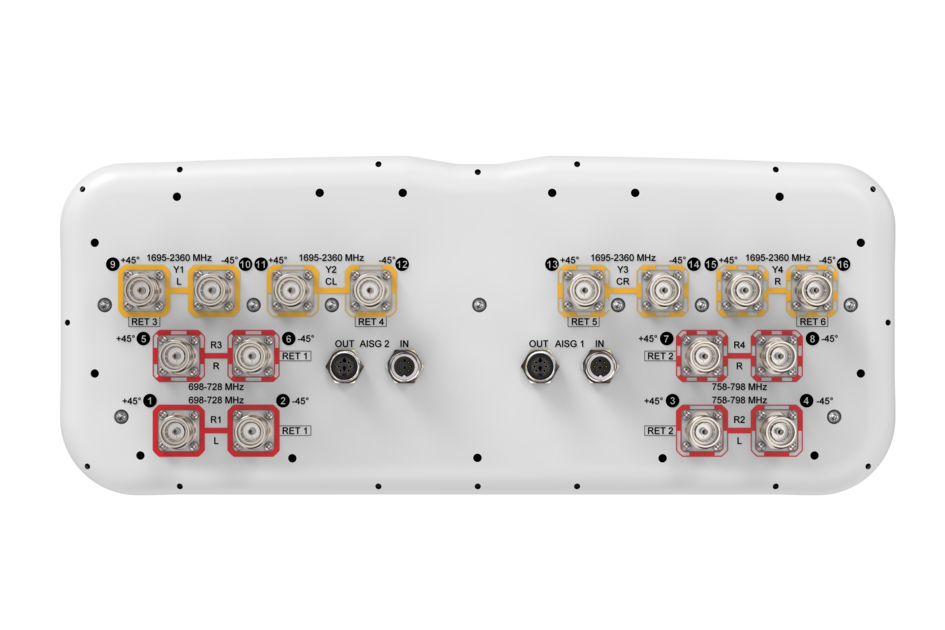
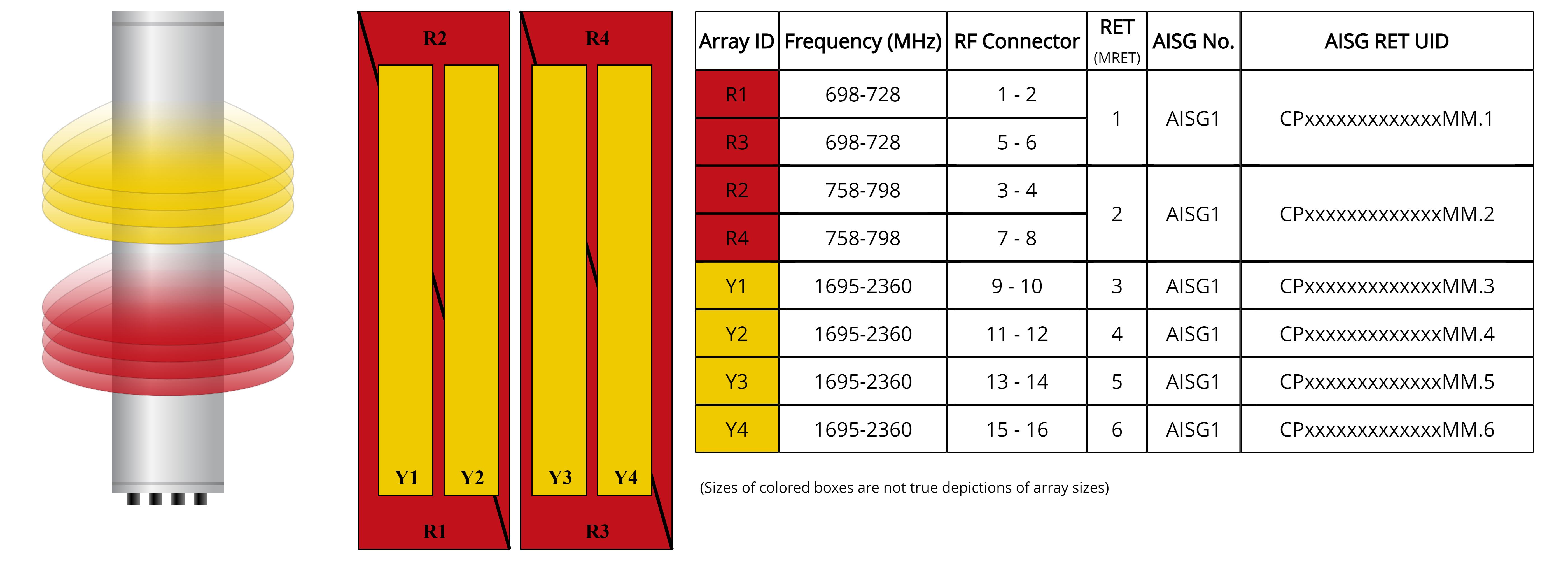
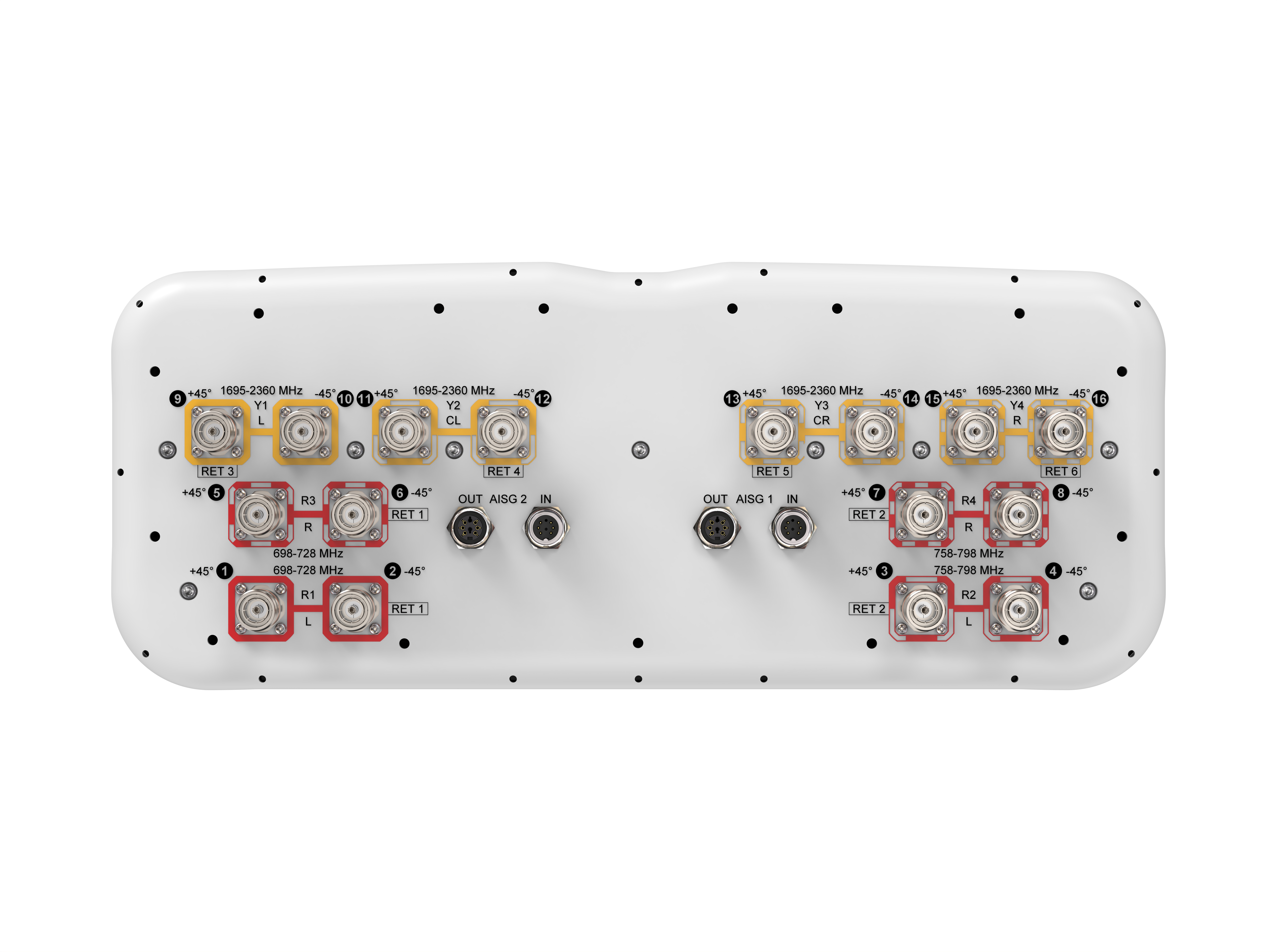
Array layout
| Click on image to enlarge. |
Port configuration
| Click on image to enlarge. |
Electrical specifications
| Impedance | 50 ohm |
| Operating Frequency Band | 698 – 798 MHz | 1695 – 2360 MHz |
| Polarization | ±45° |
| Total Input Power, maximum | 1,280 W @ 50 °C |
Electrical specifications
| R1-R3 | R2-R4 | Y1-Y4 | Y1-Y4 | Y1-Y4 | Y1-Y4 | |
| Frequency Band, MHz | 698–728 | 758–798 | 1695–1880 | 1850–1990 | 1920–2180 | 2300–2360 |
| RF Port | 1,2,5,6 | 3,4,7,8 | 9,10,11,12,13,14,15,16 | 9,10,11,12,13,14,15,16 | 9,10,11,12,13,14,15,16 | 9,10,11,12,13,14,15,16 |
| Gain, dBi | 12.3 | 12.8 | 16.0 | 16.8 | 17.5 | 18.2 |
| Beamwidth, Horizontal, degrees | 77 | 69 | 72 | 69 | 63 | 58 |
| Beamwidth, Vertical, degrees | 17.4 | 16 | 7.5 | 7 | 6.6 | 5.9 |
| Beam Tilt, degrees | 2–16 | 2–16 | 2–12 | 2–12 | 2–12 | 2–12 |
| USLS (First Lobe), dB | 18 | 17 | 15 | 17 | 18 | 20 |
| Front-to-Back Ratio at 180°, dB | 31 | 30 | 33 | 35 | 36 | 36 |
| Front-to-Back Total Power at 180° ± 30°, dB | 22 | 22 | 25 | 25 | 27 | 29 |
| CPR at Boresight, dB | 21 | 22 | 20 | 21 | 20 | 20 |
| Isolation, Cross Polarization, dB | 25 | 25 | 25 | 25 | 25 | 25 |
| Isolation, Inter-band, dB | 25 | 25 | 25 | 25 | 25 | 25 |
| VSWR | Return loss, dB | 1.5 | 14.0 | 1.5 | 14.0 | 1.5 | 14.0 | 1.5 | 14.0 | 1.5 | 14.0 | 1.5 | 14.0 |
| PIM, 3rd Order, 2 x 20 W, dBc | -150 | -150 | -150 | -150 | -150 | -150 |
| Input Power per Port at 50°C, maximum, watts | 150 | 150 | 250 | 250 | 250 | 200 |
Mechanical specifications
| Effective Projective Area (EPA), frontal | 0.47 m² | 5.059 ft² |
| Effective Projective Area (EPA), lateral | 0.14 m² | 1.507 ft² |
| Wind Loading @ Velocity, frontal | 498.0 N @ 150 km/h (112.0 lbf @ 150 km/h) |
| Wind Loading @ Velocity, lateral | 148.0 N @ 150 km/h (33.3 lbf @ 150 km/h) |
| Wind Loading @ Velocity, maximum | 597.0 N @ 150 km/h (134.2 lbf @ 150 km/h) |
| Wind Loading @ Velocity, rear | 342.0 N @ 150 km/h (76.9 lbf @ 150 km/h) |
| Wind Speed, maximum | 241 km/h (150 mph) |
Packaging and weights
| Width, packed | 565 mm | 22.244 in |
| Depth, packed | 309 mm | 12.165 in |
| Length, packed | 1686 mm | 66.378 in |
| Weight, gross | 50.4 kg | 111.113 lb |
Regulatory compliance/certifications
| Agency | Classification |
| ISO 9001:2015 | Designed, manufactured and/or distributed under this quality management system |
General specifications
| Antenna Type | Sector |
| Band | Multiband |
| Color | Light Gray (RAL 7035) |
| Grounding Type | RF connector inner conductor and body grounded to reflector and mounting bracket |
| Performance Note | Outdoor usage |
| Radome Material | Fiberglass, UV resistant |
| Radiator Material | Low loss circuit board |
| Reflector Material | Aluminum |
| RF Connector Interface | 4.3-10 Female |
| RF Connector Location | Bottom |
| RF Connector Quantity, high band | 0 |
| RF Connector Quantity, mid band | 8 |
| RF Connector Quantity, low band | 8 |
| RF Connector Quantity, total | 16 |
Remote electrical tilt (ret) information
| RET Hardware | CommRET v2 |
| RET Interface | 8-pin DIN Female | 8-pin DIN Male |
| RET Interface, quantity | 2 female | 2 male |
| Input Voltage | 10–30 Vdc |
| Internal RET | Low band (2) | Mid band (4) |
| Power Consumption, active state, maximum | 8 W |
| Power Consumption, idle state, maximum | 1 W |
| Protocol | 3GPP/AISG 2.0 (Multi-RET) |
Dimensions
| Width | 498 mm | 19.606 in |
| Depth | 197 mm | 7.756 in |
| Length | 1499 mm | 59.016 in |
| Net Weight, antenna only | 37.4 kg | 82.453 lb |
Electrical specifications
| Impedance | 50 ohm |
| Operating Frequency Band | 698 – 798 MHz | 1695 – 2360 MHz |
| Polarization | ±45° |
| Total Input Power, maximum | 1,280 W @ 50 °C |
Electrical specifications
| R1-R3 | R2-R4 | Y1-Y4 | Y1-Y4 | Y1-Y4 | Y1-Y4 | |
| Frequency Band, MHz | 698–728 | 758–798 | 1695–1880 | 1850–1990 | 1920–2180 | 2300–2360 |
| RF Port | 1,2,5,6 | 3,4,7,8 | 9,10,11,12,13,14,15,16 | 9,10,11,12,13,14,15,16 | 9,10,11,12,13,14,15,16 | 9,10,11,12,13,14,15,16 |
| Gain, dBi | 12.3 | 12.8 | 16.0 | 16.8 | 17.5 | 18.2 |
| Beamwidth, Horizontal, degrees | 77 | 69 | 72 | 69 | 63 | 58 |
| Beamwidth, Vertical, degrees | 17.4 | 16 | 7.5 | 7 | 6.6 | 5.9 |
| Beam Tilt, degrees | 2–16 | 2–16 | 2–12 | 2–12 | 2–12 | 2–12 |
| USLS (First Lobe), dB | 18 | 17 | 15 | 17 | 18 | 20 |
| Front-to-Back Ratio at 180°, dB | 31 | 30 | 33 | 35 | 36 | 36 |
| Front-to-Back Total Power at 180° ± 30°, dB | 22 | 22 | 25 | 25 | 27 | 29 |
| CPR at Boresight, dB | 21 | 22 | 20 | 21 | 20 | 20 |
| Isolation, Cross Polarization, dB | 25 | 25 | 25 | 25 | 25 | 25 |
| Isolation, Inter-band, dB | 25 | 25 | 25 | 25 | 25 | 25 |
| VSWR | Return loss, dB | 1.5 | 14.0 | 1.5 | 14.0 | 1.5 | 14.0 | 1.5 | 14.0 | 1.5 | 14.0 | 1.5 | 14.0 |
| PIM, 3rd Order, 2 x 20 W, dBc | -150 | -150 | -150 | -150 | -150 | -150 |
| Input Power per Port at 50°C, maximum, watts | 150 | 150 | 250 | 250 | 250 | 200 |
Mechanical specifications
| Effective Projective Area (EPA), frontal | 0.47 m² | 5.059 ft² |
| Effective Projective Area (EPA), lateral | 0.14 m² | 1.507 ft² |
| Wind Loading @ Velocity, frontal | 498.0 N @ 150 km/h (112.0 lbf @ 150 km/h) |
| Wind Loading @ Velocity, lateral | 148.0 N @ 150 km/h (33.3 lbf @ 150 km/h) |
| Wind Loading @ Velocity, maximum | 597.0 N @ 150 km/h (134.2 lbf @ 150 km/h) |
| Wind Loading @ Velocity, rear | 342.0 N @ 150 km/h (76.9 lbf @ 150 km/h) |
| Wind Speed, maximum | 241 km/h (150 mph) |
Packaging and weights
| Width, packed | 565 mm | 22.244 in |
| Depth, packed | 309 mm | 12.165 in |
| Length, packed | 1686 mm | 66.378 in |
| Weight, gross | 50.4 kg | 111.113 lb |
| Click on image to enlarge. |
| Click on image to enlarge. |
Regulatory compliance/certifications
| Agency | Classification |
| ISO 9001:2015 | Designed, manufactured and/or distributed under this quality management system |
Documentation & downloads
Assembly drawing
Product information
Product specification
Assembly drawing
Product compliance documentation
Product information
Product specification
Related products & accessories
Included products
Base station antennas
-
![]() BSAMNT-4 Wide Profile Antenna Downtilt Mounting Kit for 2.4 - 4.5 in (60 - 115 mm) OD round members. Kit contains one scissor top bracket set and one bottom bracket set.
BSAMNT-4 Wide Profile Antenna Downtilt Mounting Kit for 2.4 - 4.5 in (60 - 115 mm) OD round members. Kit contains one scissor top bracket set and one bottom bracket set.