E14R00P47
Dual Band Tower Mounted Amplifier, 700//850 MHz, 16 dB, 2 BTS & 4 ANT ports, AISG with 1 RET connector (1 device with 2 sub-units), with 4.3-10 connectors

Features and benefits
- New 4.3-10 connectors for improved PIM performance and size reduction
- TMA is operating in AISG & CWA mode, Alarm Current consumption CWA mode 190 mA
- 2 input ports and 4 output ports
- Designed to boost UP-Link Coverage and KPIs
- Automatic LNA by-pass function
- Connectors “in line”
- Single AISG with 1 RET connector
- 1 device with 2 sub-units
- Built in lightning protection
Specifications
Product classification
| Product Type | 1-BTS:2-ANT (Diplex) | Tower mounted amplifier |
General specifications
| Color | Gray |
| Modularity | 2-Twin |
| Mounting | Pole | Wall |
| Mounting Pipe Hardware | Band clamps (4) |
| RF Connector Interface | 4.3-10 Female |
| RF Connector Interface Body Style | Long neck |
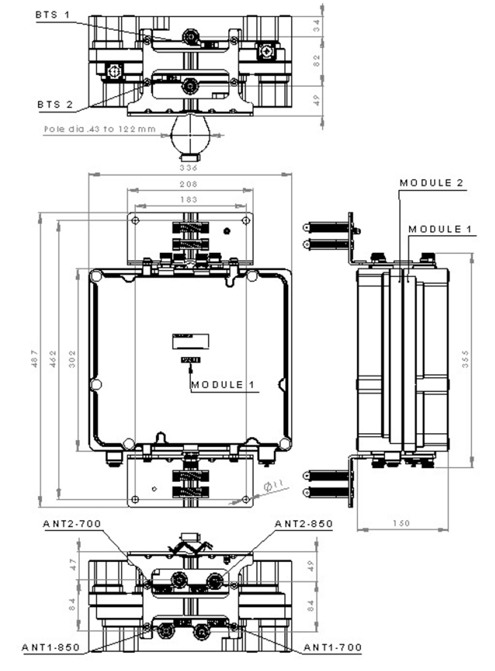
Dimensions
| Height | 150 mm | 5.906 in |
| Width | 302 mm | 11.890 in |
| Depth | 336 mm | 13.228 in |
| Ground Screw Diameter | 6 mm | 0.236 in |
| Mounting Pipe Diameter Range | 40–160 mm |
Outline drawing
| Click on image to enlarge. |
Electrical specifications
| License Band, LNA | APT 700 | CEL 850 | USA 750 |
Electrical specifications, dc power/alarm
| dc Switching/Redundancy | Yes |
| Lightning Surge Current | 10 kA |
| Lightning Surge Current Waveform | 8/20 waveform |
| Operating Current at Voltage | 240 mA @ 12 V |
| Operating Current Tolerance | ±20 mA |
| Voltage | 7–30 Vdc |
| Voltage, CWA Mode | 10–18 Vdc |
| Alarm Current, CWA Mode | 30–170 mA @ 10–18 V |
Electrical specifications, aisg
| AISG Carrier | 2.176 MHz ± 100 ppm |
| AISG Connector | 8-pin DIN Female |
| AISG Connector Standard | IEC 60130-9 |
| Default Protocol | AISG 2.0 |
| Protocol | AISG 1.1 | AISG 2.0 |
| Voltage, AISG Mode | 10–30 Vdc |
Electrical specifications
| Sub-module | 1 | 2 | 1 | 2 |
| Branch | 1 | 2 |
| Port Designation | ANT | ANT |
| AISG 2.0 Device Subunit | E15R02P25 2/4 | E15R02P25 1/3 |
| License Band | APT 700, LNA USA 750, LNA | CEL 850, LNA |
Electrical specifications, band reject
| Frequency Range, MHz | 763–775 | 851–856 |
| Attenuation, minimum, dB | 40.0 | 30.0 |
Electrical specifications, rx uplink
| Frequency Range, MHz | 703–748 | 824–845 |
| Bandwidth, MHz | 45.00 | 21.00 |
| Gain, nominal, dB | 16.5 | 15.5 |
| Gain Tolerance, dB | ±1.0 | +1.0/-1.0 |
| Gain Adjustment Range Increments, dB | 1 | |
| Noise Figure, maximum, dB | 1.7 | 2.2 |
| Noise Figure, typical, dB | 1.2 | 1.4 |
| Total Group Delay, typical, ns | 280 | 340 |
| Return Loss, typical, dB | 20 | 20 |
| Insertion Loss - Bypass Mode, typical, dB | 2.0 | 2.8 |
| Return Loss - Bypass Mode, typical, dB | 16 | 16 |
Electrical specifications, tx downlink
| Frequency Range, MHz | 758–803 | 859–890 |
| Bandwidth, MHz | 45.00 | 31.00 |
| Insertion Loss, typical, dB | 0.35 | 0.35 |
| Total Group Delay, typical, ns | 95 | 75 |
| Return Loss, typical, dB | 20 | 20 |
| RX Band Rejection, minimum, dB | 40 | 40 |
| Input Power, RMS, maximum, W | 120 | 120 |
| Input Power, PEP, maximum, W | 1,500 | 1,500 |
| 3rd Order PIM, typical, dBc | -159 | -159 |
| 3rd Order PIM Test Method | Two +43 dBm carriers | Two +43 dBm carriers |
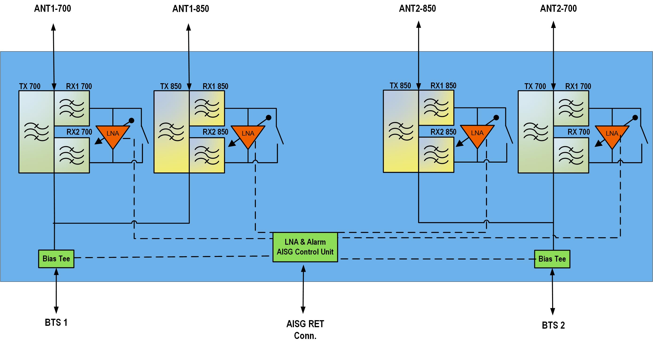
Block diagram
| Click on image to enlarge. |
Material specifications
| Finish | Painted |
Environmental specifications
| Operating Temperature | -40 °C to +65 °C (-40 °F to +149 °F) |
| Relative Humidity | Up to 100% |
| Corrosion Test Method | IEC 60068-2-11, 30 days |
| Ingress Protection Test Method | IEC 60529:2001, IP67 |
Packaging and weights
| Included | Mounting hardware |
| Volume | 15.2 L |
| Weight, net | 16.5 kg | 36.376 lb |
| Weight, without mounting hardware | 14.7 kg | 32.408 lb |
Product classification
| Product Type | 1-BTS:2-ANT (Diplex) | Tower mounted amplifier |
General specifications
| Color | Gray |
| Modularity | 2-Twin |
| Mounting | Pole | Wall |
| Mounting Pipe Hardware | Band clamps (4) |
| RF Connector Interface | 4.3-10 Female |
| RF Connector Interface Body Style | Long neck |
Dimensions
| Height | 150 mm | 5.906 in |
| Width | 302 mm | 11.890 in |
| Depth | 336 mm | 13.228 in |
| Ground Screw Diameter | 6 mm | 0.236 in |
| Mounting Pipe Diameter Range | 40–160 mm |
Electrical specifications
| License Band, LNA | APT 700 | CEL 850 | USA 750 |
Electrical specifications, dc power/alarm
| dc Switching/Redundancy | Yes |
| Lightning Surge Current | 10 kA |
| Lightning Surge Current Waveform | 8/20 waveform |
| Operating Current at Voltage | 240 mA @ 12 V |
| Operating Current Tolerance | ±20 mA |
| Voltage | 7–30 Vdc |
| Voltage, CWA Mode | 10–18 Vdc |
| Alarm Current, CWA Mode | 30–170 mA @ 10–18 V |
Electrical specifications, aisg
| AISG Carrier | 2.176 MHz ± 100 ppm |
| AISG Connector | 8-pin DIN Female |
| AISG Connector Standard | IEC 60130-9 |
| Default Protocol | AISG 2.0 |
| Protocol | AISG 1.1 | AISG 2.0 |
| Voltage, AISG Mode | 10–30 Vdc |
Electrical specifications
| Sub-module | 1 | 2 | 1 | 2 |
| Branch | 1 | 2 |
| Port Designation | ANT | ANT |
| AISG 2.0 Device Subunit | E15R02P25 2/4 | E15R02P25 1/3 |
| License Band | APT 700, LNA; USA 750, LNA | CEL 850, LNA |
Electrical specifications, band reject
| Frequency Range, MHz | 763–775 | 851–856 |
| Attenuation, minimum, dB | 40.0 | 30.0 |
Electrical specifications, rx uplink
| Frequency Range, MHz | 703–748 | 824–845 |
| Bandwidth, MHz | 45.00 | 21.00 |
| Gain, nominal, dB | 16.5 | 15.5 |
| Gain Tolerance, dB | ±1.0 | +1.0/-1.0 |
| Gain Adjustment Range Increments, dB | 1 | |
| Noise Figure, maximum, dB | 1.7 | 2.2 |
| Noise Figure, typical, dB | 1.2 | 1.4 |
| Total Group Delay, typical, ns | 280 | 340 |
| Return Loss, typical, dB | 20 | 20 |
| Insertion Loss - Bypass Mode, typical, dB | 2.0 | 2.8 |
| Return Loss - Bypass Mode, typical, dB | 16 | 16 |
Electrical specifications, tx downlink
| Frequency Range, MHz | 758–803 | 859–890 |
| Bandwidth, MHz | 45.00 | 31.00 |
| Insertion Loss, typical, dB | 0.35 | 0.35 |
| Total Group Delay, typical, ns | 95 | 75 |
| Return Loss, typical, dB | 20 | 20 |
| RX Band Rejection, minimum, dB | 40 | 40 |
| Input Power, RMS, maximum, W | 120 | 120 |
| Input Power, PEP, maximum, W | 1,500 | 1,500 |
| 3rd Order PIM, typical, dBc | -159 | -159 |
| 3rd Order PIM Test Method | Two +43 dBm carriers | Two +43 dBm carriers |
Material specifications
| Finish | Painted |
Environmental specifications
| Operating Temperature | -40 °C to +65 °C (-40 °F to +149 °F) |
| Relative Humidity | Up to 100% |
| Corrosion Test Method | IEC 60068-2-11, 30 days |
| Ingress Protection Test Method | IEC 60529:2001, IP67 |
Packaging and weights
| Included | Mounting hardware |
| Volume | 15.2 L |
| Weight, net | 16.5 kg | 36.376 lb |
| Weight, without mounting hardware | 14.7 kg | 32.408 lb |
| Click on image to enlarge. |
| Click on image to enlarge. |
Installation & videos
Installation instruction
Filter Products – Designed for PIM Excellence

Filter Products – Designed for PIM Excellence
Documentation & downloads